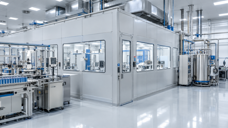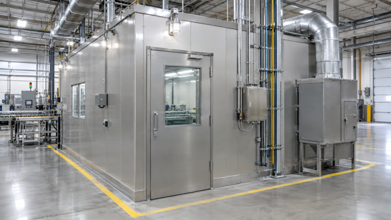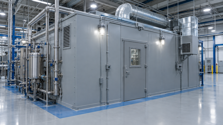
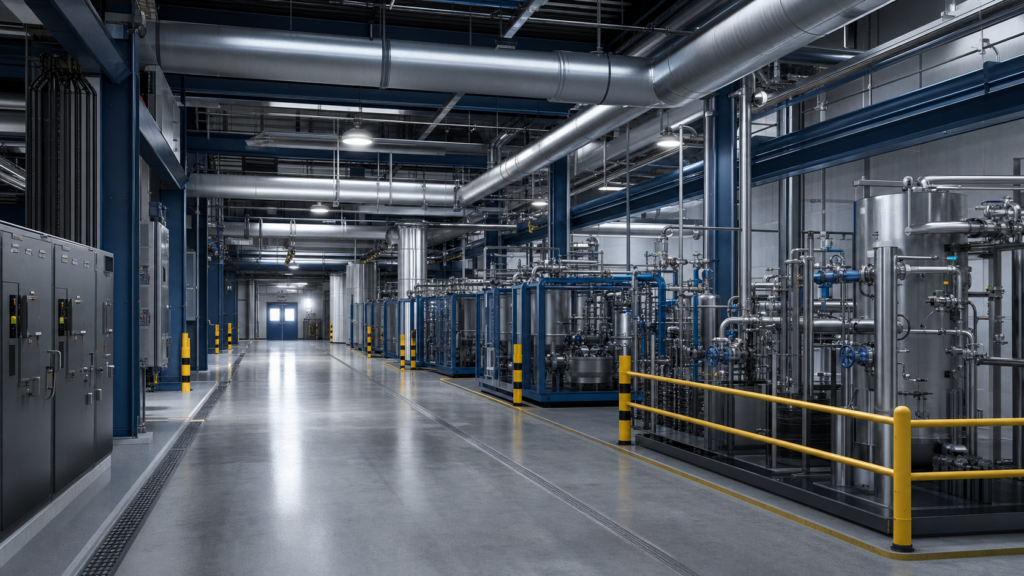
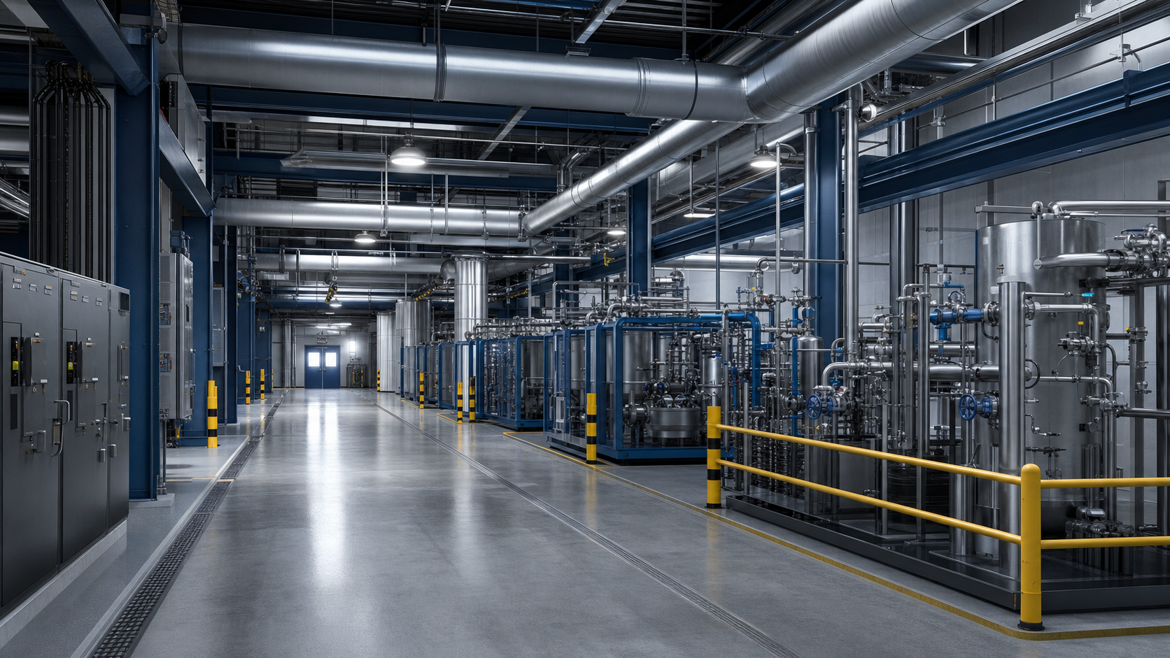
MEP engineering gives hazardous-location manufacturers a coordinated way to plan mechanical systems, electrical distribution, plumbing, controls, and safe facility operations. Instead of treating each trade as a separate package, the design team connects room conditions, equipment loads, ventilation, utilities, access, and emergency response in one buildable plan.
That coordination matters whether a project is a new processing facility, an expansion, or a retrofit inside an occupied building. A clear design basis helps owners set realistic budgets, helps installers resolve conflicts before construction, and gives the authority having jurisdiction a concise record of how the facility is intended to operate.
MEP engineering starts with a documented design basis
Begin by recording the process duty and the room-by-room operating conditions. Useful inputs include equipment heat load, airflow targets, temperature and humidity ranges, utility demand, operating schedules, cleaning methods, occupancy, access requirements, and the location of control panels. The design basis should also identify normal, start-up, shutdown, maintenance, and upset conditions.
Translate those inputs into measurable criteria. For example, define the required air changes, pressure relationships, filtration level, electrical connected load, available fault current, drainage capacity, and acceptable temperature band. These values provide a practical basis for equipment selection and reduce late revisions caused by assumptions that were never written down.
How MEP engineering coordinates airflow and utilities
Airflow planning is more than choosing a fan. The team should map supply, return, exhaust, make-up air, filtration, heat recovery, and discharge points while considering door swings, equipment clearances, maintenance paths, and building structure. Pressure relationships should support the room strategy without creating doors that are difficult to open or air movement that carries dust and heat into adjacent areas.
Utilities deserve the same level of coordination. Lay out process water, compressed air, drains, cooling connections, electrical feeders, data lines, and emergency services on a shared model or drawing set. Provide isolation points, labels, drip protection, access panels, and replacement routes. C1D1 Labs can also coordinate low-temperature and explosion-proof freezer solutions with room utilities when temperature-controlled staging is part of the facility plan.
MEP engineering for electrical and life-safety interfaces
Electrical design should account for equipment starting current, motor loads, control power, grounding, bonding, disconnect locations, cable routing, and future capacity. In a classified area, select listed equipment and wiring methods for the location, document the classification boundaries, and keep ordinary electrical components outside those boundaries wherever the layout permits.
Mechanical and electrical systems also need defined life-safety responses. The cause-and-effect matrix may specify how ventilation, access control, alarms, equipment shutdowns, emergency power, and monitoring respond to a detected event or loss of utility. Coordinate these interfaces with the fire protection plan; C1D1 Labs provides fire protection engineering for insurance risk reduction as part of broader facility planning.
For electrical installations in hazardous locations, review OSHA’s electrical requirements for hazardous locations and confirm the requirements adopted by the local authority. The project team should track code interpretations, equipment listings, inspection points, and approval comments in the design record.
Commissioning MEP engineering systems before production
Commissioning verifies that the systems work together, not merely that individual devices turn on. Test airflow direction, pressure relationships, temperature control, alarms, fan and pump rotation, valve operation, sensor calibration, emergency stops, interlocks, loss-of-power behavior, and restart sequences. Record baseline readings for airflow, pressure, temperature, vibration, and electrical load so operations staff can identify drift later.
- Confirm equipment nameplates, disconnect labels, grounding, access clearances, and service documentation.
- Test permissives for ventilation, utility pressure, equipment status, access position, and downstream readiness.
- Verify alarm annunciation, remote monitoring, emergency power transfer, and the approved reset sequence.
- Collect as-built drawings, calibration records, inspection reports, spare-parts lists, and training sign-offs.
Resolve deficiencies before handover and assign an owner for each corrective action. A short, witnessed retest is usually less disruptive than discovering a coordination gap during the first production campaign.
Design MEP engineering systems for maintainability
Lifecycle performance depends on safe access to filters, dampers, coils, sensors, pumps, panels, drains, and isolation valves. Leave room for inspection and replacement, keep service points visible, protect controls from washdown or impact, and use durable identification that matches the drawings. Good access lowers downtime and helps technicians complete preventive work on schedule.
Finally, connect the design record to management of change. A new piece of equipment, revised room use, changed operating temperature, or higher production rate can alter airflow, electrical load, drainage, and emergency response. Recheck the design basis before approving the change, then update drawings, procedures, training, and inspection plans.
C1D1 Labs helps manufacturers coordinate rooms, equipment, utilities, safety functions, and documentation for dependable industrial operations. Strong MEP engineering starts with measurable criteria, resolves trade interfaces early, and ends with commissioning records that operators can use.