Hazardous location electrical design is one of the most scrutinized parts of any modern processing buildout. When a room, booth, or enclosed process area is classified as Class I, Division 1 (C1D1), the electrical scope is no longer a simple matter of placing convenience outlets and lighting fixtures. Every energized component within the defined boundary must be selected, installed, and coordinated around the presence of ignitable vapors during normal operations. For hydrocarbon and solvent-based processing environments, that means electrical planning has to be integrated with ventilation, gas detection, equipment layout, and the building’s overall fire protection strategy from day one.
For facility owners, engineers, and contractors, the challenge is not just technical correctness. It is also documentation, inspection readiness, and long-term serviceability. Authorities Having Jurisdiction (AHJs), design professionals, and insurers typically expect the electrical design narrative to align with the hazardous materials inventory, the booth or room construction details, and the operating sequence of the process equipment. A well-coordinated design reduces rework, avoids late-stage field changes, and gives operators a safer and more stable production environment.
Why C1D1 Electrical Classification Changes the Entire Design Approach
Under NFPA 70, National Electrical Code, Class I locations are spaces where flammable gases or vapors may be present in the air in quantities sufficient to produce explosive or ignitable mixtures. Division 1 applies where those concentrations are expected under normal operating conditions, or where maintenance, repair, or equipment failure could frequently release them. That classification immediately changes wiring methods, equipment listings, sealing requirements, disconnect strategies, motor selection, and the placement of instrumentation.
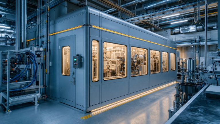
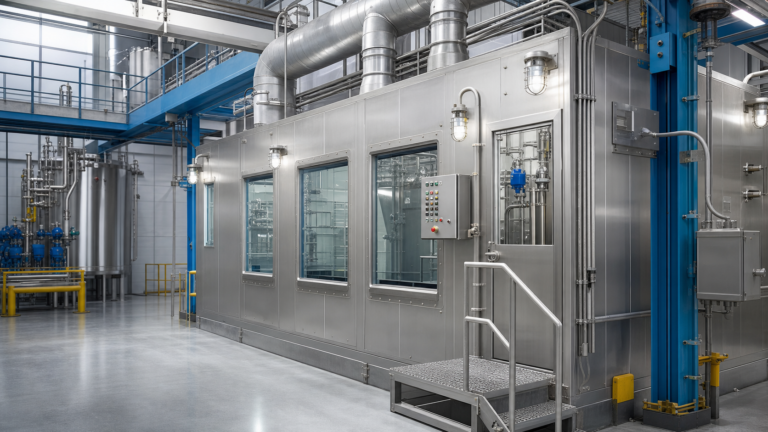
In practice, a compliant design begins by defining the exact classified envelope. That envelope may be the interior of a code-compliant enclosure, a dedicated room, or a smaller boundary around specific process equipment depending on the process, ventilation design, and engineering basis. This is why many facilities begin with a purpose-built C1D1 booth rather than trying to adapt a general industrial room after equipment procurement. Once the boundary is clear, the electrical engineer can map every device that must either be rated for the classification or relocated outside the hazardous zone.

Purpose-built C1D1 enclosures help define the classified area and simplify hazardous location electrical coordination.
Key Electrical Components That Need Early Coordination
Several electrical elements routinely create problems when they are addressed too late. Lighting is one of the most obvious examples. Fixtures installed inside the classified area must carry the appropriate hazardous location listing and be compatible with the environmental conditions of the enclosure, including washdown potential, heat, corrosion, and service access. The same principle applies to switches, operator interfaces, receptacles, junction boxes, motor controls, sensors, and conduit seals. Even a small non-rated device installed in the wrong location can trigger plan corrections or failed inspections.
Motors and rotating equipment deserve particular attention. Exhaust fans, circulation blowers, and some support utilities may sit inside or interface directly with the classified zone. Their ratings, control logic, and shutdown sequence should be coordinated with the ventilation design and the gas detection strategy. Facilities deploying hydrocarbon processing equipment also need to consider how chillers, heaters, pumps, recovery skids, and control panels interact with the classified boundary. In many successful layouts, higher-maintenance controls are intentionally kept outside the C1D1 space whenever the process design allows, reducing service complexity and component cost.
Sealing fittings and conduit routing are another area where code intent matters. Hazardous location seals are not decorative accessories; they are part of the ignition protection system. Proper sealing helps limit vapor migration through the raceway system and maintains the integrity of explosionproof assemblies. Field crews need clear installation details, because even a solid engineering design can be undermined by poor conduit routing or missing seals at final trim-out.
Interlocks, Detection, and Emergency Shutdown Logic
Electrical compliance in C1D1 environments is not limited to hardware selection. It also depends on how the system behaves during normal operation, upset conditions, and alarm events. Gas detection, emergency stop devices, and fan status interlocks should all be tied into a predictable operating sequence. When a detector senses vapor above a defined threshold, the control logic typically needs to shut down nonessential equipment, maintain or increase hazardous exhaust, and place the room in a safer state pending investigation.
Those sequences should be documented clearly enough that the mechanical engineer, fire protection engineer, controls integrator, and electrician are all working from the same assumptions. This coordination becomes especially important in larger rooms where multiple subsystems interact. A strong facility design package usually treats electrical controls as part of the life-safety framework rather than as a separate afterthought. The result is a design that is easier to commission and easier for the AHJ to review.
Design teams should also review the implications of hazardous materials provisions in the International Fire Code, since room classification, allowable quantities, alarm interfaces, and exhaust performance often influence electrical decisions. In other words, the electrical plan cannot be fully correct unless it matches the fire code basis of design.

Ventilation equipment, gas detection, and electrical shutdown logic must operate as one coordinated system.
Documentation, Inspection Readiness, and Long-Term Reliability
One of the clearest signs of a mature C1D1 project is disciplined documentation. Equipment cut sheets, panel schedules, one-line diagrams, area classification drawings, control narratives, and sequence-of-operations summaries all help inspectors and reviewers understand the design intent. They also help the operations team troubleshoot issues months later without guessing how the room was supposed to function.
For long-term reliability, the best designs reduce unnecessary complexity inside the classified zone. Place serviceable components outside the hazard boundary where possible. Standardize device families. Label disconnects and interlocks clearly. Confirm that the booth, process skid, and building systems use compatible alarm logic. And make sure replacement parts can be sourced without redesigning the room. These decisions improve uptime and reduce the temptation to introduce noncompliant field modifications later.
Teams should also benchmark their design philosophy against insurer-facing guidance such as FM Global Data Sheets when applicable, especially for property protection, utility reliability, and loss prevention review. While not a substitute for adopted codes, these references can strengthen the engineering basis behind equipment placement and resilience decisions.
Ultimately, C1D1 electrical design is about more than buying explosionproof parts. It is about building a coordinated process environment where classification boundaries, code requirements, control logic, and equipment selection all reinforce one another. When the electrical plan is aligned with the booth design, the ventilation concept, and the fire protection strategy, facilities are better positioned to move through review, commissioning, and operation with fewer surprises and a much stronger compliance posture.