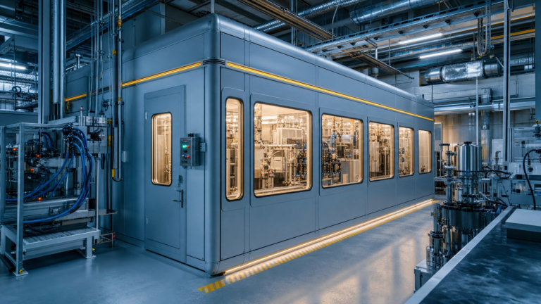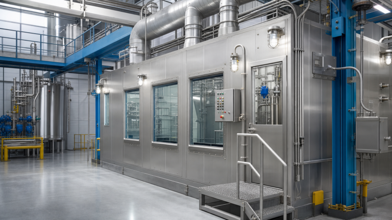
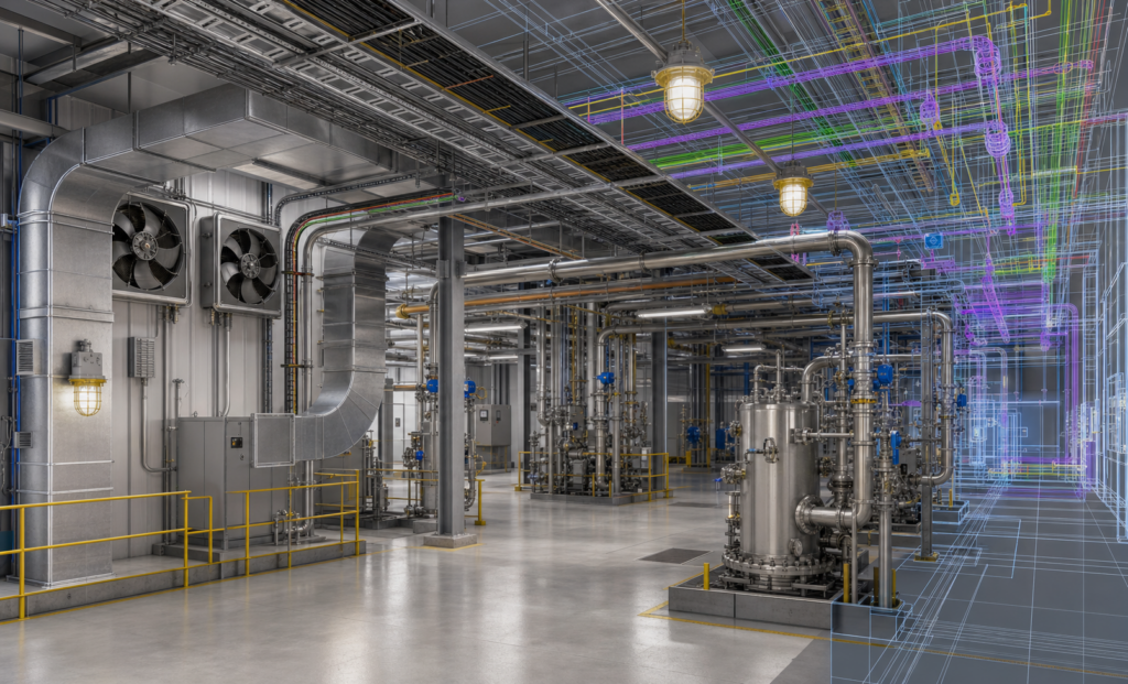
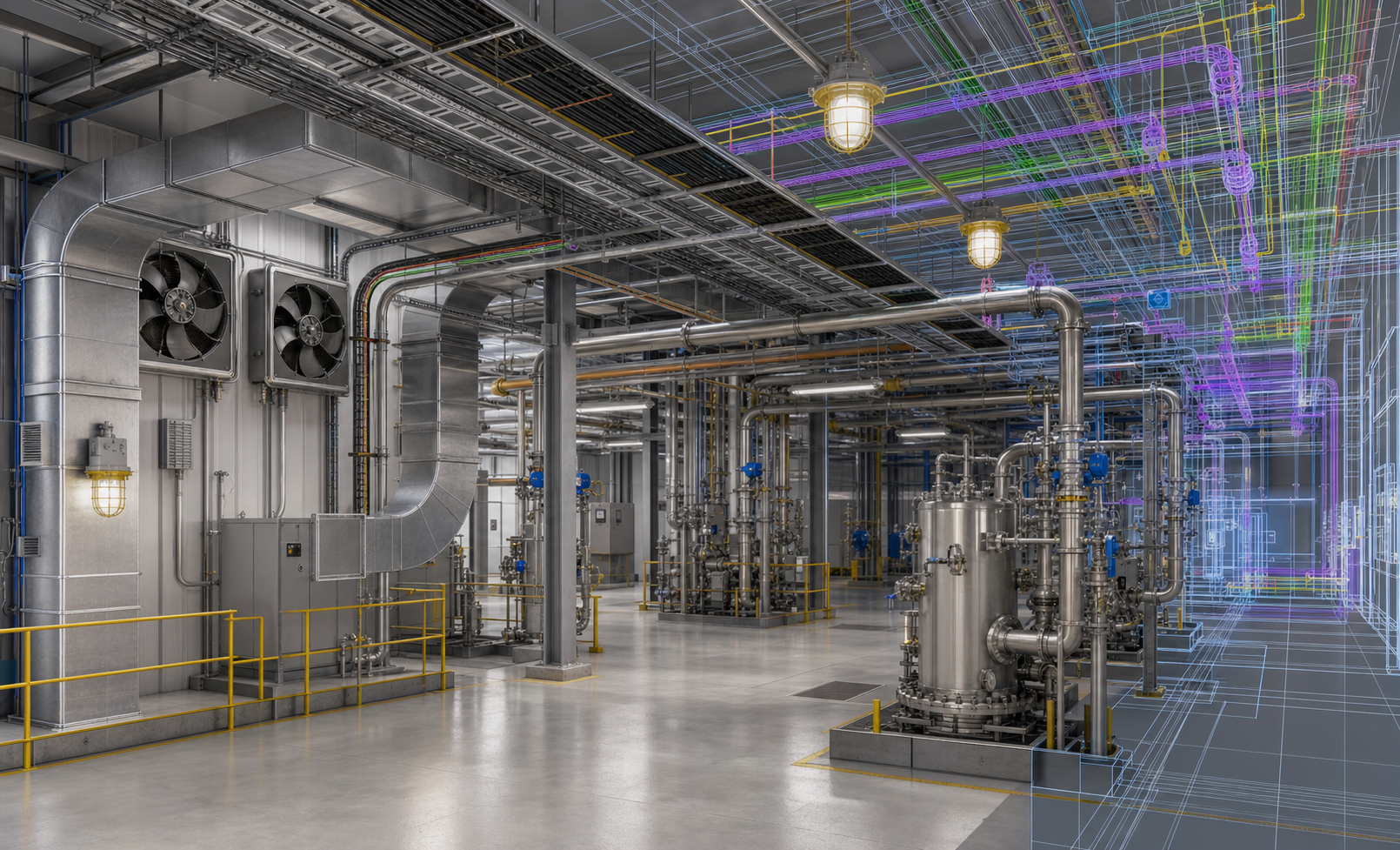
MEP engineering is the discipline that turns a hazardous-location manufacturing concept into a buildable, inspectable facility by coordinating mechanical ventilation, electrical power and controls, and plumbing/utility systems into one code-aligned design.
For owners, EPC teams, and facility managers, the fastest schedule wins usually come from early coordination: defining the hazard classification basis, selecting the right equipment protection concepts, and documenting how each trade will install, test, and maintain the systems over the life of the building.
MEP engineering and the hazard-classification basis
Strong MEP engineering starts with a clear written basis of design (BOD) that summarizes the processes, materials, and operating envelope that drive the hazard classification for each room or area. The BOD should identify the assumed classification approach (for example, class/division style classification), the boundaries of each classified zone, and the design assumptions that keep conditions stable (ventilation rates, enclosure ratings, temperature limits, housekeeping, etc.).
When the classification basis changes late—because of a layout shift, new equipment, or revised operations—MEP redesign can ripple across duct routing, cable tray, lighting, and device selection. Treat classification as an input to MEP, not an output.
MEP engineering for ventilation, pressure control, and capture
Mechanical design often becomes the critical-path item in hazardous facilities because it connects life safety, process performance, and energy use. In many projects, MEP engineering must solve three objectives at once:
- Air movement to maintain safe concentrations and stable operating conditions.
- Directional airflow to keep emissions contained and protect adjacent spaces.
- Maintainability with access for filter changes, belt service, and inspection.
During coordination, confirm where air is supplied and exhausted, how make-up air is tempered, and what happens during abnormal events such as fan failure or emergency shutdown. If relief paths, louvers, or backdraft dampers are needed, show them clearly in plans and sections so installers do not improvise in the field.
MEP engineering for electrical systems in hazardous locations
Electrical scope for a hazardous facility is more than selecting “rugged” components. MEP engineering should document wiring methods, sealing requirements, and equipment protection concepts so the installation matches the classification basis and the authority having jurisdiction can inspect it efficiently.
A practical approach is to create an electrical matrix that lists each space, its classification, permitted equipment types, and typical devices (lighting, receptacles, motors, VFDs, sensors). Tie that matrix back to one-line diagrams and panel schedules so procurement and construction stay aligned.
For a regulatory starting point, OSHA’s electrical standard includes a section on hazardous (classified) locations that frames requirements for electrical installations in such areas (OSHA 29 CFR 1910.307).
MEP engineering coordination with fire protection and life safety
In hazardous-location manufacturing, MEP decisions can either simplify or complicate the fire protection strategy. For example, ventilation shutdown logic, damper actuation, and smoke control interfaces may affect detection and suppression sequences. Align the MEP control narrative with the life-safety sequence early, and ensure the drawings show device locations and control panel interfaces.
If you are building a risk-reduction case for stakeholders or insurers, it also helps to coordinate with a dedicated fire protection engineer; see our overview of fire protection engineering for insurance risk reduction.
MEP engineering deliverables that reduce change orders
The best MEP engineering packages translate intent into installer-ready documents. Beyond the usual plans and schedules, consider including:
- Room-based system diagrams that show supply/exhaust paths, key dampers, and control points.
- Commissioning checklists for airflow verification, control sequence testing, and interlock validation.
- Equipment access clearances and service routes in coordination with architectural and structural constraints.
- Tagged control narrative that matches point names on the drawings and in the BAS/PLC logic.
Finally, include a short “inspection roadmap” sheet: what the inspector should look for, where labels and seals are indicated, and how critical installations are verified. This is a low-effort addition that can save days during turnover.
Bottom line: When MEP engineering is driven by a clear classification basis, coordinated in 3D, and documented with an installer-and-inspector mindset, hazardous facilities become easier to build, easier to permit, and more reliable to operate.