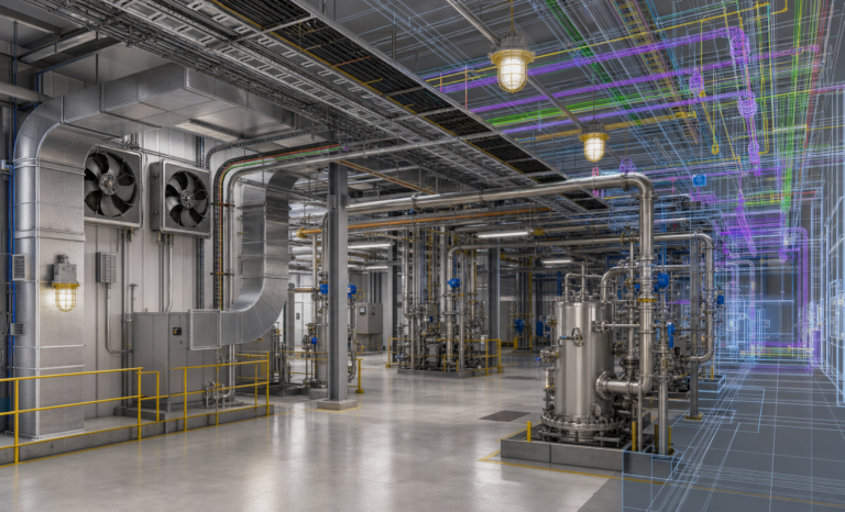
Utility planning is one of the most underestimated phases in an industrial processing project. Teams often focus first on equipment lead times, throughput targets, and room dimensions, but the real coordination challenge emerges when the facility must support electrical distribution, exhaust airflow, chilled services, heating loads, drainage, and control integration at the same time. In ethanol processing environments, those utility decisions should be made before major equipment arrives, not after skids, tanks, centrifuges, and freezers are already in the building.
A code-driven planning approach starts by treating the processing room as an engineered process environment rather than a simple tenant improvement. That means mapping utility demand around the actual equipment sequence, the anticipated solvent-handling workflow, and the requirements of the adopted fire and building codes. When this step is skipped, facility owners usually encounter the same pattern: electrical panels land in the wrong location, duct runs become longer than expected, condensate routing turns inefficient, and room pressurization drifts away from the assumptions made during permit review.

The first planning layer is load mapping. Every major piece of ethanol processing equipment should be entered into a utility schedule that captures voltage, phase, amperage, connected load, heat rejection, ventilation implications, and clearance demands. This schedule becomes the bridge between process design and facility engineering. It also gives the design team a reliable basis for one-line diagrams, panel schedules, and mechanical sizing. Without that shared document, the room may technically fit the equipment while still failing to support safe operation.
Electrical demand deserves early attention because it tends to expand as the room matures. Initial planning may include centrifuges, recovery systems, jacketed tanks, pumps, and low-temperature storage. Later additions often bring inline instrumentation, control cabinets, auxiliary heaters, vacuum systems, and transfer skids. If the original design leaves no spare capacity, every future change becomes a field workaround. Good utility planning reserves capacity where it matters and keeps service paths clean enough to support orderly expansion.
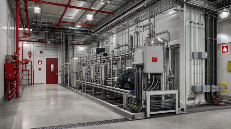
The next major layer is ventilation coordination. Even in facilities where the primary focus is process efficiency, the room must still satisfy the fundamental expectations of the fire code official and design reviewer. Exhaust, makeup air, room pressure relationships, and duct routing must all align with the use of the space and the classification strategy adopted by the engineering team. Designers should evaluate how the room interfaces with adjacent spaces, whether solvent storage is integrated or separated, and how airflow will be maintained during both normal operation and upset conditions. The NFPA 30 framework for flammable and combustible liquids remains one of the key technical references in this step.
Mechanical coordination also determines whether the facility will be stable under real operating conditions. Jacketed tanks, cold processing equipment, and recovery hardware all introduce thermal loads that can shift rapidly across a production day. A room that is nominally cooled may still develop hot zones around pumps or control enclosures, while low-temperature process areas may generate condensation issues on nearby surfaces or piping. These conditions affect not just equipment reliability but also corrosion resistance, sanitation planning, and service life. Mapping the utility loads early gives the engineering team time to separate heat-producing equipment from temperature-sensitive steps and to protect control systems accordingly.

Drainage and floor utility design are equally important. In many projects, trenching and housekeeping pads are finalized too late, after major equipment selections are already locked. That sequence creates expensive redesigns and encourages temporary hoses, awkward floor penetrations, and service points that interfere with operator movement. A better approach is to define transfer paths, washdown areas, and service connections while the equipment schedule is still being refined. That supports a cleaner plan review package and helps maintain orderly circulation through the room.
Another frequent design miss is inadequate service clearance. Throughput equipment may physically fit against a wall on paper, but facilities still need room for maintenance access, filter changes, vessel loading, pump replacement, and safe technician movement. In technical reviews, cramped layouts often reveal that the project was designed around nominal equipment dimensions instead of operational envelopes. This is why early coordination with building permit planning and field installation sequencing matters. The permit set should show not just what is being installed, but how the room will actually function over time.
For projects seeking a durable, insurable, and scalable facility, utility planning should also reflect the broader risk strategy of the site. Fire protection engineering is not limited to alarm devices and suppression interfaces. It includes the discipline of reducing ignition opportunities, preserving predictable airflow, limiting retrofit complexity, and aligning utility routing with the hazard analysis that supports the room. Guidance from the International Fire Code and the FM Global data sheet library can help teams benchmark protection strategy, utility reliability, and loss-prevention design decisions.
The strongest ethanol processing rooms are rarely the ones with the most equipment. They are the ones where engineering decisions were made in the right order. Utility planning before equipment arrival gives teams time to validate connected loads, confirm airflow assumptions, preserve access clearances, and avoid rushed field fixes that undermine compliance. It also improves communication between ownership, engineers, contractors, and code officials because everyone is working from the same technical map.
At the project level, that discipline translates into fewer change orders, smoother inspections, and a more credible facility narrative during permit review. For operators and owners, it means the room performs closer to its intended capacity from day one. For engineers, it means the design basis stays intact as procurement and construction move forward. And for facilities expected to scale, it creates a foundation that can absorb future equipment additions without forcing a wholesale redesign of the room.
In practical terms, utility planning should begin with a coordinated equipment matrix, followed by preliminary one-line power design, exhaust and makeup air assumptions, thermal load review, floor utility routing, and maintenance envelope confirmation. That work can then be cross-checked against the adopted building and fire code path, supported by a documented engineering rationale, and tied back to the full room layout. When done correctly, the processing room is not just ready to receive equipment. It is ready to support safe, stable, code-aligned operation from the first commissioning sequence onward. For teams evaluating a new room or retrofit, a formal review of fire protection engineering support and utility coordination can prevent costly rework long before installation begins.